Engine compartment cooling fan (3S-GTE)
System circuit

Location of engine compartment cooling fan components

On-vehicle inspection
Low temperature (below 45.5°C (113.9°F))
-
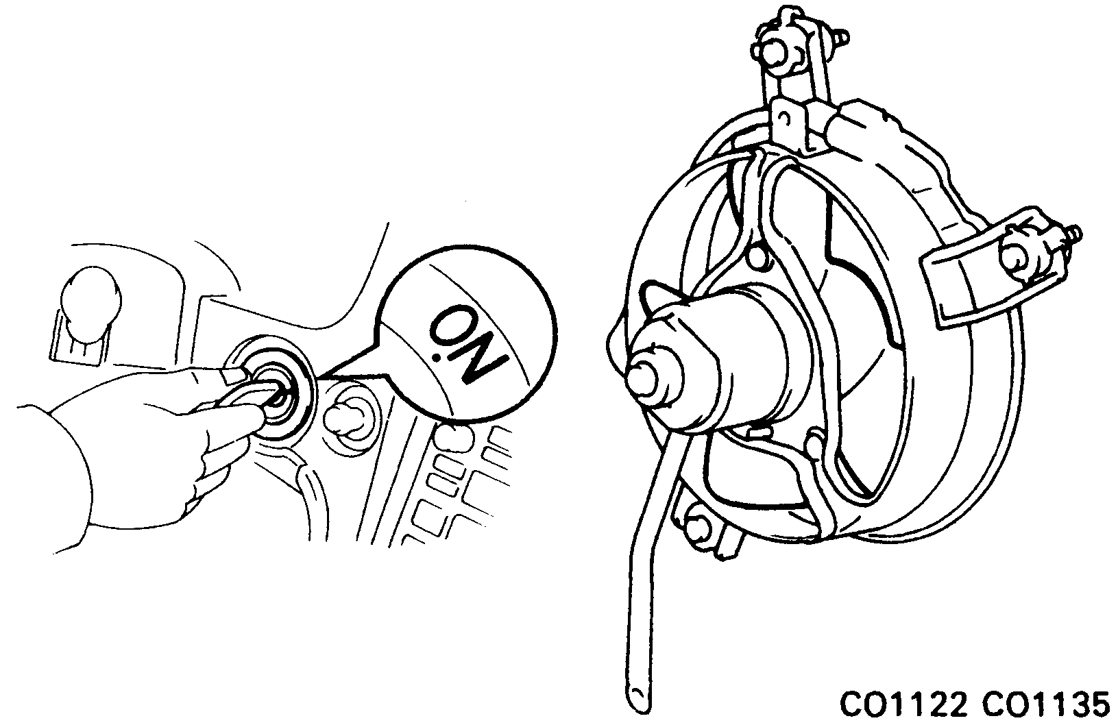
Turn ignition switch "ON".
Check that the cooling fan stops.
If not, check the cooling fan relays and engine compartment temperature sensor, and check for a separated connector or severed wire between the cooling fan relay and engine compartment temperature sensor.
-
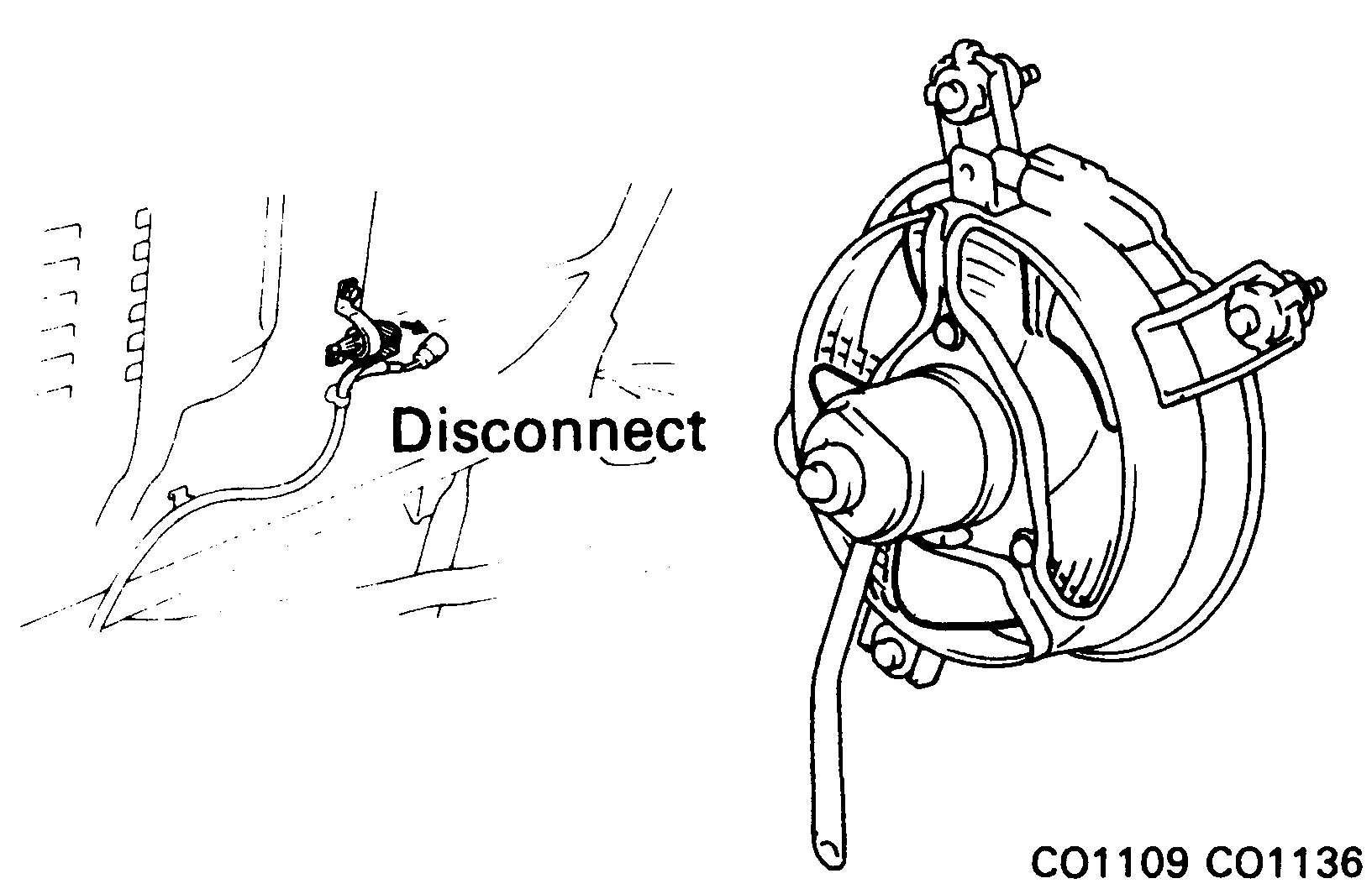
Disconnect engine compartment temperature sensor connector.
Check that the cooling fan rotates.
If not, check the ignition main relay, cooling fan relays, cooling fan ECU, cooling fan and fuses, and check for a short circuit between the cooling fan relay and engine compartment temperature sensor.
-
Connect engine compartment temperature sensor connector.
High temperature (above 62.5°C (144.5°F))
-
Start engine.
- Raise coolant temperature to above 62.5°C (144.5°F).
-
Check that the cooling fan rotates.
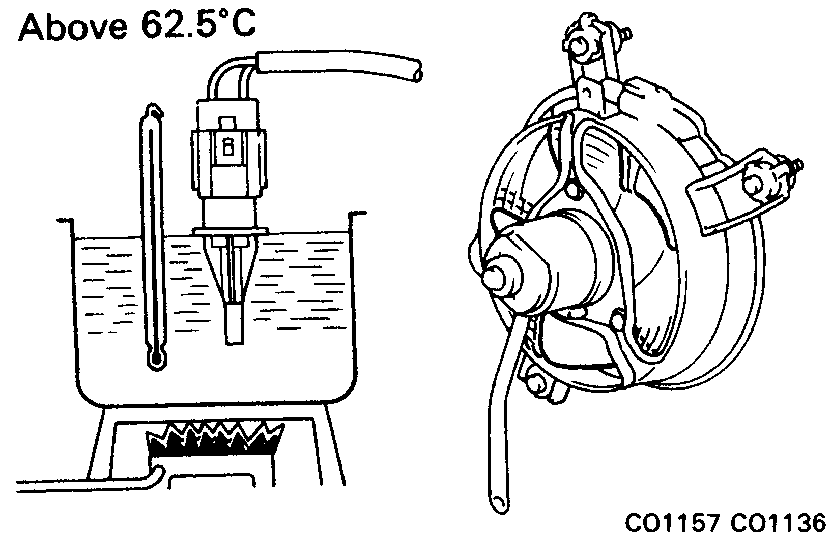
If not, replace the engine compartment temperature sensor.
Inspection of engine compartment cooling fan components
-
Inspect cooling fan ECU for circuit.
Disconnect the cooling fan ECU connector, and check the connector on the wiring harness side as shown in the chart.
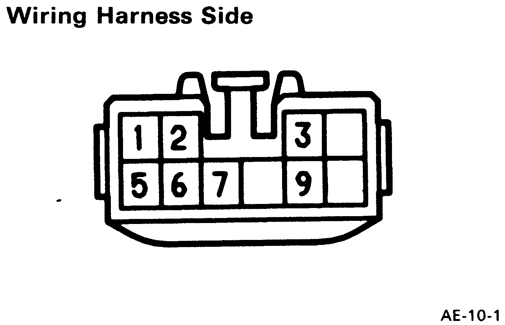
Check for Tester connection Condition Specified value Continuity 1 – Ground – Continuity Voltage 2 – Ground Ignition switch ON Battery voltage Voltage 3 – Ground Ignition switch ON Battery voltage Resistance 5 – 6 Coolant temp. 20°C (68°F) Approx. 2.45 kΩ Coolant temp. 57.5°C (135.5°F) Approx. 0.63 kΩ Coolant temp. 80°C (176°F) Approx. 0.32 kΩ Voltage 7 – Ground Ignition switch ON Battery voltage Continuity 9 – Ground Ignition switch ON Battery voltage -
Inspect ignition main relay ("IGN"). (See Ignition main relay "IGN")
-
Inspect cooling fan main relay ("VENT"). (See Radiator cooling fans (w/ A/C) › Inspection of radiator cooling fan components)
Check the relay the same way as for the No.1 Cooling Fan Relay.
-
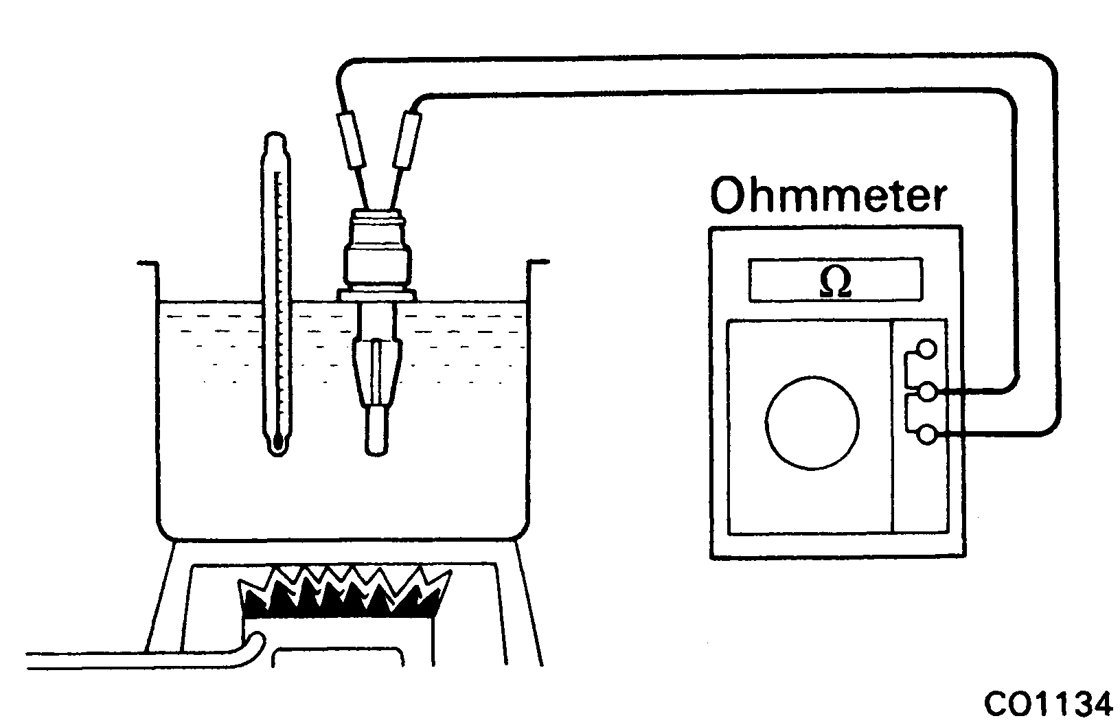
Inspect engine compartment temperature sensor.
Using an ohmmeter, measure the resistance between the terminals.
Resistance:
- Approx. 2.45 kΩ at 20°C (68°F)
- Approx. 0.63 kΩ at 57.5°C (135.5°F)
- Approx. 0.32 kΩ at 80°C (176°F)
If resistance is not as specified, replace the sensor.
-
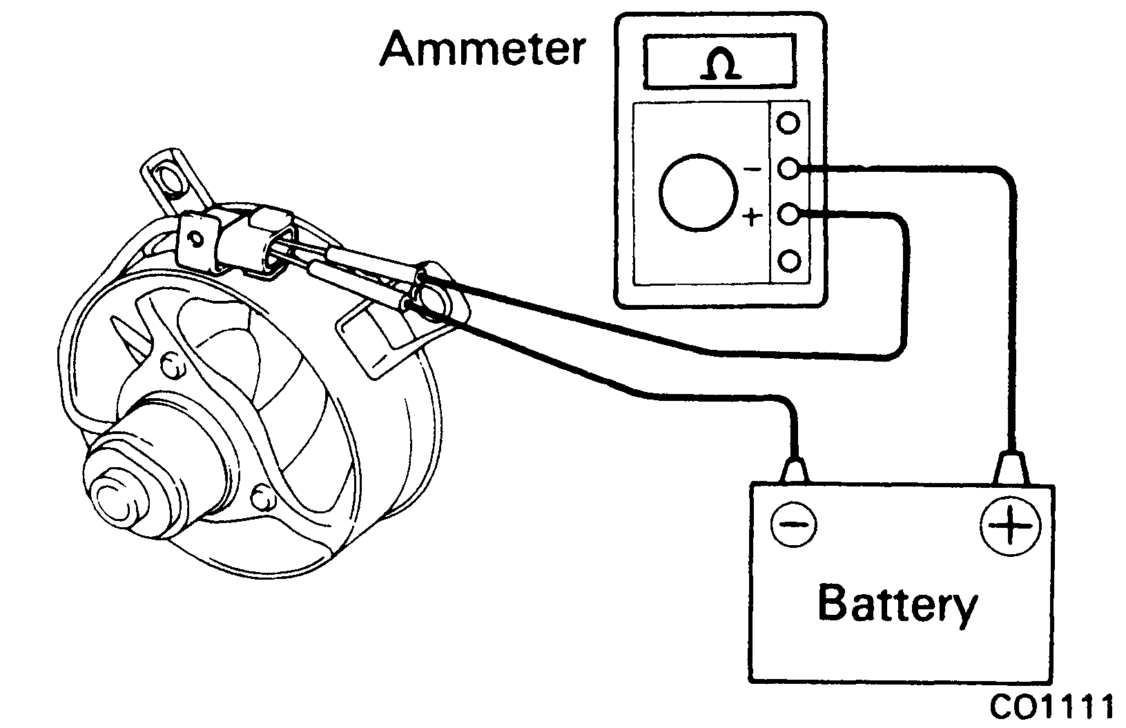
Inspect engine compartment cooling fan.
- Connect battery and ammeter to the cooling fan connector.
- Check that the cooling fan rotates smoothly, and check the reading on the ammeter.
Standard amperage: 3.1 – 4.3 A
Removal of engine compartment cooling fan

-
Disconnect cable from negative terminal of battery.
Caution
Work must be started after approx. 20 seconds or longer from the time the ignition switch is turned to the "LOCK" position and the negative (
–) terminal cable is disconnected from the battery. -
Remove RH engine hood side panel.
- Remove No.1 and No.2 air intake connectors. (See Intercooler, steps 4, 5)
- Disconnect engine compartment cooling fan connector.
-
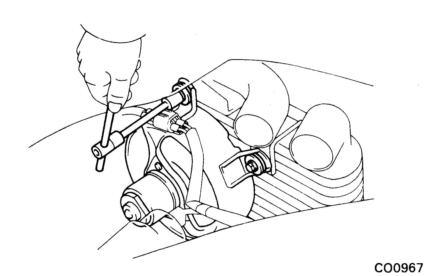
Remove engine compartment cooling fan.
Loosen the three bolts, and remove the cooling fan.
Components

Disassembly of engine compartment cooling fan
-
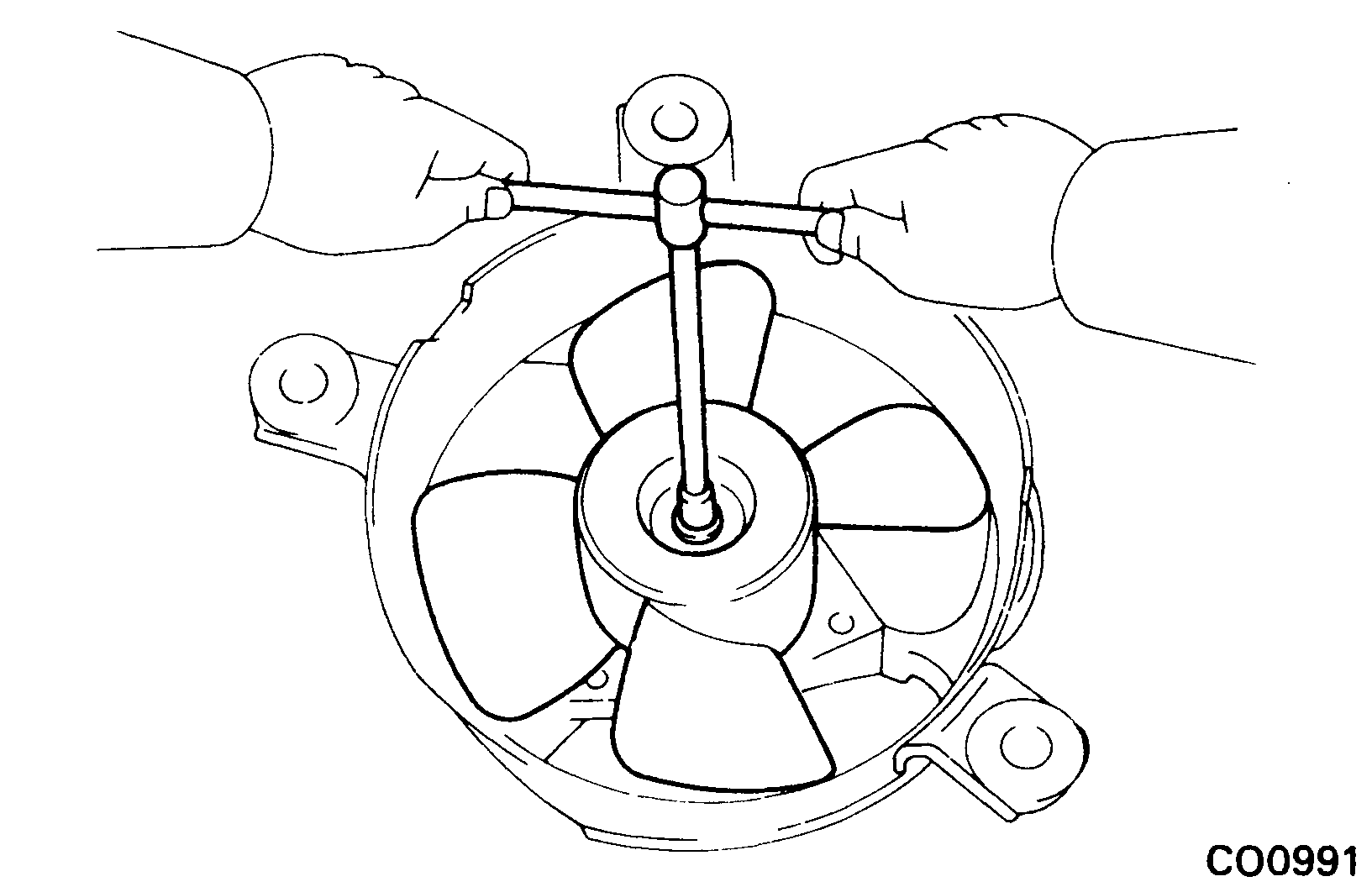
Remove fan.
Remove the nut and fan.
-
Remove fan motor.
Remove the three screws and fan motor.
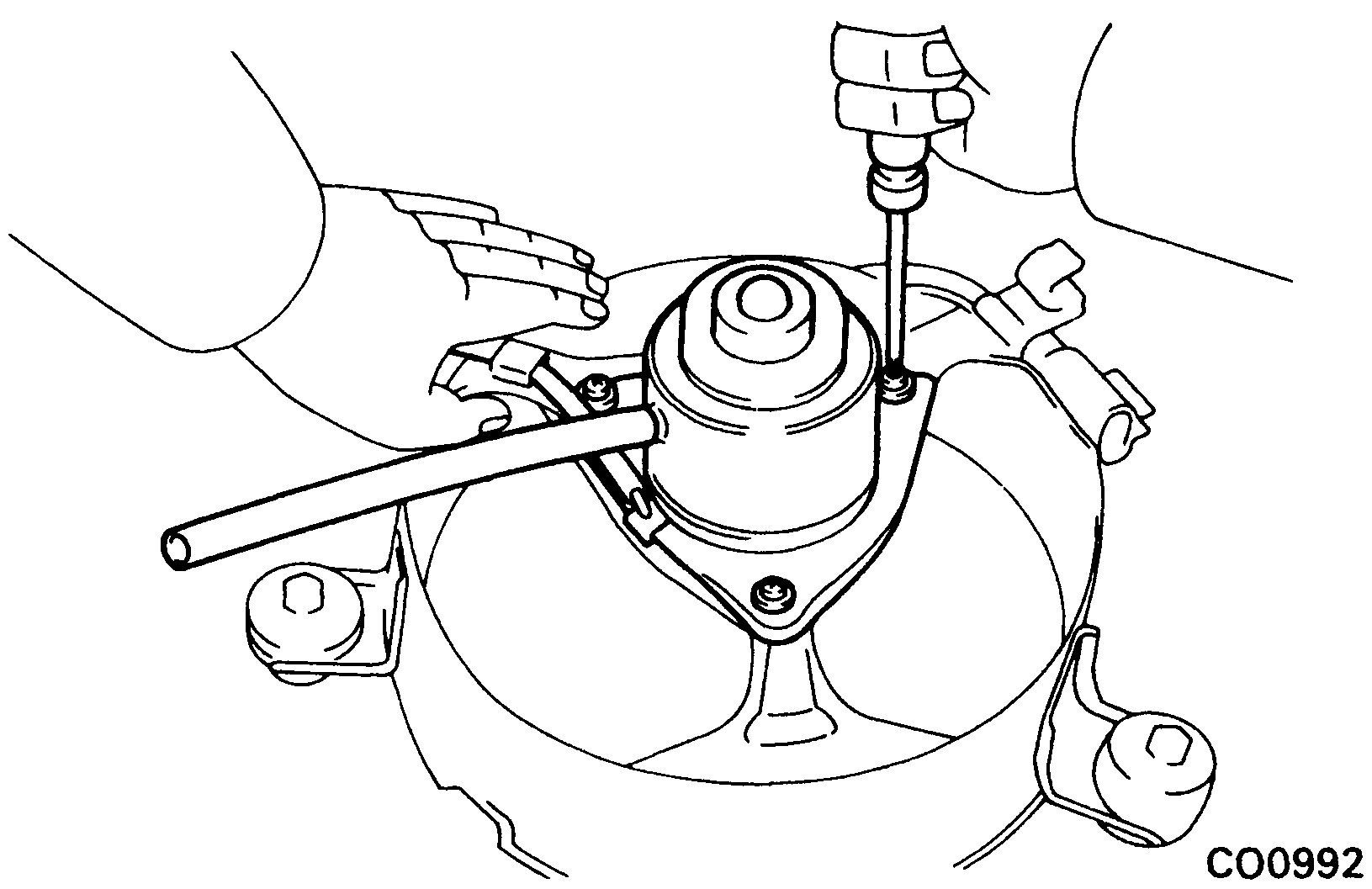
Assembly of engine compartment cooling fan
- Install fan motor.
- Install fan.
Installation of engine compartment cooling fan
(See Removal of engine compartment cooling fan)
-
Install engine compartment cooling fan.
Install the cooling fan with the three bolts.
-
Connect engine compartment cooling fan connector.
- Install No.1 and No.2 air intake connectors. (See Intercooler › Installation of intercooler, steps 10, 11)
- Install RH engine hood side panel.
- Connect cable to negative terminal of battery.